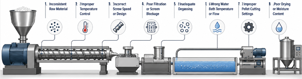
Poor pellet quality in an Engineering Plastic Pelletising Production Line is primarily caused by improper process parameter settings, raw material inconsistencies, equipment wear, and inadequate die-face cutting control. Identifying and resolving these root causes is essential for maintaining dimensional uniformity, surface finish, and mechanical performance of the final plastic granules.
Whether you are running a Twin Screw Pelletising System for glass-fiber-reinforced nylon or a high-throughput Plastic Granule Extrusion Line for flame-retardant ABS, pellet quality defects translate directly into downstream processing problems and customer rejections. This guide breaks down every major cause — with data and practical examples — so your team can act fast and keep production on spec.
Content
- 1 The Most Common Pellet Quality Defects and What They Signal
- 2 Raw Material Issues: The Hidden Starting Point of Quality Problems
- 3 Process Parameter Deviations That Degrade Pellet Consistency
- 4 Screw Design and Wear: A Root Cause That Is Easy to Overlook
- 5 Die Plate Design and Pellet Cutting System Performance
- 6 Degassing and Venting: Preventing Internal Voids and Bubbles
- 7 Cooling System Failures and Pellet Deformation
- 8 Feeding System Instability and Its Effect on Pellet Uniformity
- 9 Practical Checklist: How to Systematically Reduce Pellet Quality Defects
- 10 About Kunwei: Professional Engineering Plastic Pelletising Production Line Manufacturer
- 11 Frequently Asked Questions
The Most Common Pellet Quality Defects and What They Signal
Before diagnosing root causes, it helps to classify the defect type. Different defect signatures point to different system failures.
| Defect Type | Visual / Physical Sign | Primary Root Cause |
|---|---|---|
| Tails / Stringing | Long fiber attached to pellet | Dull cutter blades or wrong cutting speed |
| Fines / Dust | Powder fraction >1% by weight | Overly high cutting speed or melt temp too low |
| Irregular Length | CV > 5% in pellet length | Unstable screw speed or melt pressure fluctuation |
| Voids / Bubbles | Internal cavities under cross-section | Moisture in raw material or insufficient degassing |
| Surface Roughness | Matte, uneven surface | Shear overheating or contamination |
| Discolouration | Yellow or brown tinge | Thermal degradation from excessive residence time |
Raw Material Issues: The Hidden Starting Point of Quality Problems
Many pellet quality failures in an Engineering Plastic Compounding Line originate before the material even enters the extruder barrel. Moisture content is the most frequent culprit. Engineering resins such as PA6, PA66, PBT, and PC are hygroscopic — they absorb atmospheric moisture rapidly. Moisture levels above 0.05% w/w in polycarbonate, for instance, cause hydrolytic chain scission, generating bubbles and dramatically reducing molecular weight.
- PA6/PA66: dry to ≤ 0.20% moisture before feeding
- PC / PBT: dry to ≤ 0.02–0.05% moisture
- PPS, PEEK: typically require 4–6 hours at 120–150 °C in a dehumidifying dryer
Beyond moisture, contamination from foreign polymers, metal fragments, or off-spec additives creates hard inclusions and melt flow rate (MFR) inconsistencies. Even a 0.1% cross-contamination of HDPE into a PA66 batch can produce surface fish-eyes and reduce impact strength by 15–20%. Rigorous raw material inspection and silo management are non-negotiable.
Process Parameter Deviations That Degrade Pellet Consistency
Even with perfect raw materials, incorrect process settings on a High Torque Pelletising Machine will produce off-spec pellets. The key variables and their acceptable operating windows are described below.
Melt Temperature and Residence Time
Running the barrel temperature too high or maintaining a slow screw speed extends residence time beyond the thermal stability window of the resin. For glass-fiber-reinforced PA66, exceeding 300 °C for more than 90 seconds measurably reduces tensile strength by 8–12% and causes yellowing. Conversely, too-low melt temperatures increase melt viscosity and produce rough pellet surfaces and incomplete mixing.
Screw Speed and Feed Rate Matching
On a twin-screw compounder, the ratio of feed rate to screw speed determines the degree of fill and shear intensity. Underfeeding at high screw speeds generates excessive frictional heat and fines. Overfeeding at low speeds causes insufficient melting and unmixed particles. Most engineering plastic compounding processes operate at a specific throughput of 5–15 kg/h per rpm, depending on the extruder diameter and material type.
Die Pressure and Melt Pump Stability
Pressure fluctuations at the die — often caused by screw wear, partial die-hole blockage, or unstable feeding — result in variable strand diameter and irregular pellet length. Die pressure should be held within ±2–3 bar of the setpoint for dimensionally consistent pellets. Installing a melt pump between the extruder and die significantly reduces these fluctuations in high-viscosity engineering plastic applications.
Impact of Process Parameter Deviations on Pellet Defect Rate (%)
Figure 1: Estimated contribution of each deviation type to pellet defect rate in a typical engineering plastic compounding line
Screw Design and Wear: A Root Cause That Is Easy to Overlook
The screw configuration of a Twin Screw Pelletising System directly governs mixing quality, dispersion of additives, and melt homogeneity. Using an inappropriate screw design — for example, too many conveying elements and too few kneading blocks for a glass-fiber-filled compound — results in poor fibre distribution and strength variability in pellets.
Equally important is screw wear. Corrosive and abrasive engineering plastics (e.g., PPS with 40% glass fibre, or halogen-containing flame retardants) can reduce the screw flight clearance from a nominal 0.1–0.2 mm to over 0.5 mm within 3,000–5,000 operating hours. This increased clearance causes backflow, reduces conveying efficiency, and produces pellets with inconsistent density. Regular measurement with air gauges or dial indicators is necessary, and worn screws should be refurbished or replaced promptly.
- Inspect screw OD every 2,000 hours for abrasive compounds
- Use bimetallic or tungsten-carbide-coated screws for highly abrasive fills
- Check barrel bore for ovality — replace if clearance exceeds OEM tolerance by 50%
Die Plate Design and Pellet Cutting System Performance
The die plate and cutting unit are the final determinants of pellet geometry. Poor die plate design — uneven hole spacing, inconsistent hole diameter, or inadequate heating — produces strands of varying cross-section that the cutter cannot handle uniformly.
Underwater Pelletising vs. Strand Pelletising
Underwater pelletising (UWP) systems are widely used in high-volume Plastic Granule Extrusion Lines for engineering plastics because they produce near-spherical pellets and eliminate strand breakage. However, they require precise water temperature control (typically 50–80 °C for engineering plastics) and cutter hub contact force calibration. Too-cold process water causes cracking; too warm leads to pellet sticking and lensing.
Strand pelletising lines are preferred when pellet shape flexibility is needed, but are more sensitive to strand tension variation. A broken strand during production immediately generates a batch of off-length or misshapen pellets until the operator re-threads the die.
Cutter Blade Maintenance
Blade sharpness is critical. A cutting edge with a measured wear flat of more than 0.05 mm begins to produce tails and fines rather than clean cuts. In a typical high-throughput line running glass-filled polyamide, blades may need replacement every 250–400 hours. Establishing a blade change schedule — rather than reacting to defect appearance — is the most effective quality assurance measure for the cutting system.
Degassing and Venting: Preventing Internal Voids and Bubbles
Volatiles trapped inside pellets — whether from residual moisture, low-boiling solvents in recycled streams, or decomposition by-products from additives — manifest as internal voids or surface blisters. Effective venting is particularly critical in Technical Plastic Recycling Lines where incoming material may contain surface coatings, labels, or processing aids from previous lives.
Twin-screw extruders can be configured with one or more atmospheric or vacuum vent ports. Vacuum venting at –0.08 to –0.095 MPa removes low-molecular-weight volatiles that atmospheric venting cannot. For high-moisture-load streams, a side-devolatilisation unit or a two-stage extruder arrangement is sometimes required. Blocked or partially blocked vent ports — a surprisingly common maintenance oversight — are responsible for a significant portion of void-related pellet defects in practice.
Cooling System Failures and Pellet Deformation
After cutting, pellets must be cooled quickly and evenly to lock in their shape and prevent blocking (sticking together). In a water-ring or underwater pelletising system, the cooling water volume, temperature, and flow path around each pellet must be uniform. Inadequate cooling leads to:
- Blocking: pellets fuse together in the dryer or collection bag, especially with high-crystallisation-rate materials like POM
- Deformation: flat or kidney-shaped pellets instead of cylindrical ones, causing flow problems in downstream moulding equipment
- Internal stress: rapid quenching without controlled annealing generates residual stress that can cause micro-cracking during storage or shipping
Centrifugal dryers following the water bath must remove surface moisture effectively. Residual surface water above 0.1% w/w leads to re-agglomeration during pneumatic conveying and silo storage.
Feeding System Instability and Its Effect on Pellet Uniformity
Volumetric or gravimetric feeders that deliver an inconsistent mass flow to the extruder introduce periodic surging — rhythmic fluctuations in screw torque and melt pressure that translate directly into pellet length variation. Gravimetric (loss-in-weight) feeders are strongly preferred for engineering plastic compounding because they maintain feed accuracy to within ±0.5% even when bulk density varies between material lots.
Side-feeding of fibres (glass fibre, carbon fibre) or high-density fillers (barium sulfate, talc) must be calibrated separately and fed at rates matched to the main screw speed. A side-feeder speed ratio deviation of more than 3% from the designed setpoint will produce filler content variation and inconsistent pellet weight.
Pellet Length CV (%) vs. Feed Rate Fluctuation (%)
Figure 2: Pellet length coefficient of variation increases non-linearly as feeder fluctuation rises above 2%
Practical Checklist: How to Systematically Reduce Pellet Quality Defects
A structured approach to pellet quality troubleshooting should cover all major subsystems of the production line:
- Raw material verification — Confirm moisture content, MFR, and contamination level before each batch
- Dryer performance audit — Verify dew point output; confirm residence time at temperature is adequate
- Screw and barrel inspection — Measure clearance; check for wear, corrosion, or heat zone failure
- Process parameter review — Compare current setpoints against validated process window; correct any drift
- Vent port check — Inspect for polymer buildup blocking vacuum ports; re-seal if vacuum is degraded
- Die plate inspection — Check for partially blocked holes, die deposit buildup, or temperature non-uniformity
- Cutter blade and hub condition — Measure wear; replace blades on schedule rather than on failure
- Cooling system check — Verify water temperature, flow rate, and dryer discharge moisture
- Feeder calibration — Run calibration checks on all gravimetric feeders; confirm side-feeder speed ratios
- Pellet sampling and measurement — Conduct SPC on length, diameter, bulk density, and fines fraction at minimum once per shift
About Kunwei: Professional Engineering Plastic Pelletising Production Line Manufacturer
Sichuan Kunwei Langsheng Extrusion Intelligent Equipment Co., Ltd. is headquartered and produces at its base in Dujiangyan, Chengdu, Sichuan, with branch offices in Changzhou (Jiangsu), Dongguan (Guangdong), and Yuyao (Zhejiang). This geographic coverage ensures full-reach support for domestic chemical, pharmaceutical, and blending modification customers, providing comprehensive sales and after-sales services nationwide.
As a dedicated Engineering Plastic Pelletising Production Line manufacturer and supplier, Kunwei employs a team of chemical machinery and electrical engineers with more than a decade of deep industry experience. The company specialises in high-torque twin-screw extruders, serving the pharmaceutical, fine chemicals, and blending modification fields with a proven track record.
Kunwei has engineered the highest specific torque in the modification industry — 14 Nm/cm³ — and supports extruder specifications spanning 8 mm to 177 mm, giving customers access to a model range broad enough for laboratory-scale trials through full commercial production. With industry-leading precision spare parts and the ability to design complete Engineering Plastic Compounding Lines, Kunwei delivers high-quality, high-torque, high-speed twin-screw extrusion systems tailored to the demands of fine chemical and advanced material producers.

