


 ENG
 中文简体
 русский
 عربى
Put an 80% calcium carbonate masterbatch and a 30% talc-filled compound on the same co-rotating twin-screw platform and they behave like two different machines — because they are two different processes. In a filler masterbatch the polymer is the minor phase: roughly one part resin has to wet out, disperse and bind four to five parts of abrasive mineral powder. Every equipment decision on the line follows from that ratio.
The short answer: filler masterbatch is manufactured by coating the mineral surface, dosing the powder into a twin-screw extruder downstream of the melted resin, dispersing it at 70–85 wt% loading, devolatilizing under vacuum, and pelletizing the melt into 2–3 mm granules that are cooled, classified and packed.
Content
- 1 The Manufacturing Route in Four Stages
- 2 Step 1: Formulation and Surface Treatment
- 3 Step 2: Feeding the Powder Without Flooding the Throat
- 4 Step 3: Melting, Dispersing and Devolatilizing
- 5 Step 4: Pelletizing, Cooling and Classification
- 6 Quality Control: What Actually Gets Measured
- 7 Where Filler Masterbatch Lines Usually Go Wrong
- 8 Frequently Asked Questions
- 8.1 What is the difference between filler masterbatch and a filled compound?
- 8.2 How much calcium carbonate can a twin-screw extruder handle?
- 8.3 Why is the filler fed downstream instead of into the main hopper?
- 8.4 Which pelletizing method is used for filler masterbatch?
- 8.5 Why does filler masterbatch generate dust?
- 8.6 What screw configuration suits high filler masterbatch?
The Manufacturing Route in Four Stages
Start with the conclusion: a filler masterbatch line is a dosing problem wrapped around a dispersing problem, finished by a pelletizing problem. Each stage has an output you can measure long before the material reaches the packing valve.
- Pre-treatment – surface coating and premix of filler, carrier resin, coupling agent and lubricant.
- Feeding – gravimetric dosing of resin into the main throat; the mineral enters downstream through a side feeder.
- Compounding – melting, dispersive mixing, vacuum devolatilization and pressure build-up at the die.
- Forming – die-face or strand pelletizing, cooling, screening and packing.
Step 1: Formulation and Surface Treatment
Ground calcium carbonate in the 1–10 µm range is the most common filler, with talc, kaolin, barium sulfate and wollastonite used where density, stiffness or chemical resistance matters more than cost. Raw CaCO3 is hydrophilic and agglomerates easily, so it is normally coated with 0.8–2% stearic acid (or a stearate/silane system) during grinding. That coating lowers surface energy, reduces the torque needed to wet each particle and is the single biggest lever on how high a loading the line can reach.
The carrier resin sets the melt strength that pelletizing depends on. PP homopolymer in the 5–15 g/10 min MFI range is typical for 80% CaCO3 grades; LDPE or LLDPE appears in softer, more flexible masterbatches. Additives are small in percentage but decisive in effect: a coupling agent for talc or wollastonite, PE wax or zinc stearate as internal lubricant, and an antioxidant package sized for the thermal history.
Step 2: Feeding the Powder Without Flooding the Throat
On a high-loading line the mineral does not go into the main feed throat with the resin. Four things go wrong when it does: the throat floods and the screw starves, the powder coats the pellets and the feed slips, the first flights wear at an unacceptable rate, and the filler gets compacted before it ever sees molten polymer — which makes dispersion harder rather than easier.
The conventional arrangement is a loss-in-weight feeder dropping resin and additives into barrel 1, three to five L/D of melting, then a side feeder injecting coated powder into the melt at roughly 8–16 L/D. Running that side feeder under slight negative pressure pulls powder into the flights instead of letting it dust back out of the vent, and it also raises the bulk density of the feed stream — a detail that matters when you are moving tonnes per hour of 0.9 g/cm³ powder. The mechanism is described in more detail in this note on negative-pressure powder feeding.
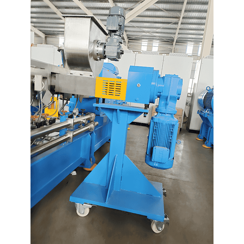 Kunwei Side Feeder for Twin-Screw Extrusion LinesDownstream feeding system for powder, short fiber, or premix, with optional negative-pressure feeding to improve bulk density and feeding efficiency.View Product →
Worth checking during a factory acceptance test: screw geometry matched to the actual powder, the venting arrangement above the side feeder, and whether a low-level alarm stops the main feeder before the barrel runs lean. Bulk density can vary by 10% between carbonate deliveries, so gravimetric rather than volumetric dosing is not optional at this loading.
Step 3: Melting, Dispersing and Devolatilizing
Screw configuration does the dispersive work. A typical filler masterbatch screw carries a conveying and melting zone, two or three kneading blocks at 30°, 45° and 90° for dispersive mixing, distributive elements to redistribute the melt, a vacuum zone, and a final pressure-building section. Mixing intensity comes from the number and stagger angle of the kneading discs, not from screw speed alone — running faster with a weak configuration only adds shear heat.
The temperature window is narrower than it looks. For PP/CaCO3, melt temperatures of roughly 190–210 °C wet out the filler without decomposing the stearate coating; above about 250 °C that coating breaks down, and the symptoms — odour, voids, silver streaks and black specks — are then blamed on the filler instead of the profile. Vacuum devolatilization at 200–400 mbar (abs) removes the 0.1–0.3% moisture that fine powder carries in from the atmosphere.
Wear is the real cost driver. At 80% loading, barrels and screws see abrasive duty that a 20% compound never imposes: bimetallic or HIP liners, carbide or PTA-hardfaced screw elements and a realistic spare-parts budget belong in the process design, not in the afterthought list. Throughput on this duty is normally torque-limited rather than volume-limited, which is why specific torque — 9 to 14 Nm/cm³ on current machines — decides how much filler a given frame size can carry.
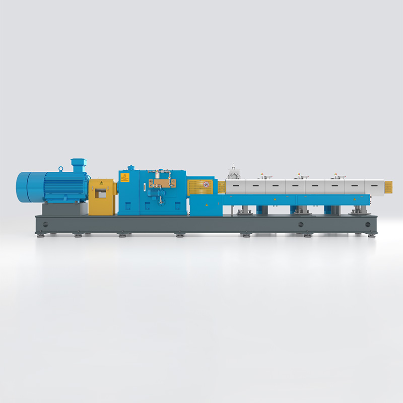 KTS High Performance Engineering Plastic Extrusion Line SeriesHigh-performance engineering plastic extrusion line series with published model parameters for specific torque, speed, torque, and motor power.View Product →
Step 4: Pelletizing, Cooling and Classification
Filler masterbatch melts have low melt strength, so most lines use die-face cutting rather than strand pelletizing: the melt passes a multi-hole die and is cut immediately in a water ring, then carried to a centrifugal dryer. Strand lines still make sense at lower loadings and where a cylindrical pellet is preferred, but above roughly 70% filler the strands turn brittle and break up in the water bath.
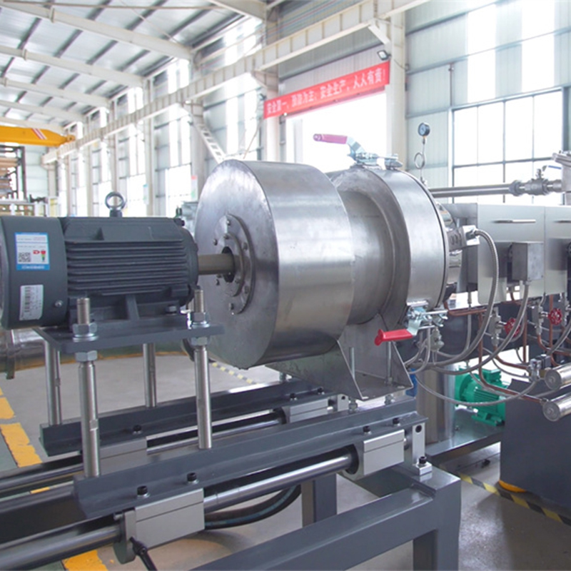 Water Ring Hot Face Cutting Pelletizing SystemDownstream pelletizing system that cuts melt at the die face and cools particles in a water ring before pipeline transport.View Product →
Downstream of the dryer, a vibrating screen strips out fines and oversized pellets — typical dispatch specifications allow no more than about 0.5% fines at the packing valve. Die hole diameter, water temperature and cutter speed together set the 2–3 mm pellet size that customers' downstream feeding systems expect.
Quality Control: What Actually Gets Measured
Filler masterbatch is bought on numbers, so the line has to prove them batch by batch. The checks below are the ones converters ask for most often.
| Parameter | Typical target | Why it matters | Method |
|---|---|---|---|
| Filler (ash) content | ±1% of nominal | Changes cost and mechanical properties directly | Ash test, ISO 3451 / TGA |
| Moisture | ≤0.15% | Voids, silver streaks, bubble defects | Karl Fischer or loss on drying |
| Dispersion | No agglomerates above spec | Surface defects and weak points in the part | Pressure filter value, DIN EN 13900-5 |
| Bulk density | 0.9–1.3 g/cm³ | Feeding stability at the converter | Graduated cylinder |
| Fines content | ≤0.5% | Dust, bridging and feed interruptions | Screen analysis |
Where Filler Masterbatch Lines Usually Go Wrong
Most troubleshooting calls come back to four symptoms, and none of them is really about the filler:
- Rising die pressure at stable output – worn screw elements or a partly plugged screen pack; watch the pressure trend rather than the absolute value.
- Black specks – degraded coating or stagnant melt in a dead zone, often at the die or the vacuum dome.
- Dust at packing – classifier overload or a cutter running out of tolerance, which also means lost yield.
- Output below nameplate – usually a torque ceiling reached with a screw design too aggressive for the powder's bulk density.
When the existing hardware cannot be pushed further, the choice is between a new line and a rebuild. Reworking a large-capacity high-filler granulation production line — new screw geometry, a properly sized side feeder, more vacuum capacity — is often the cheaper route to higher output on the same frame.
Frequently Asked Questions
What is the difference between filler masterbatch and a filled compound?
A filled compound carries 10–40% mineral and is sold ready to process. A filler masterbatch is a concentrate at 70–85% mineral in a carrier resin, let down at the converter, so it is manufactured with tighter dispersive mixing and heavier wear protection.
How much calcium carbonate can a twin-screw extruder handle?
Commercially 75–85% by weight for coated CaCO3 in PP. Above that, the melt no longer forms a continuous phase well enough to pelletize reliably, and torque and wear rise sharply.
Why is the filler fed downstream instead of into the main hopper?
Downstream feeding lets the resin melt first, keeps the feed throat from flooding, and puts the abrasive powder into the melt where it can be wetted and dispersed rather than compacted in the first flights.
Which pelletizing method is used for filler masterbatch?
Die-face water ring cutting dominates above 70% loading because the melt has too little strength for strands. Strand pelletizing remains a valid choice for lower-filled grades.
Why does filler masterbatch generate dust?
Fines come from brittle pellets breaking at the die face, from cutter wear and from classifier overloading. A screen analysis at packing is the fastest way to trace the source.
What screw configuration suits high filler masterbatch?
Conveying and melting elements, two or three kneading blocks with increasing stagger angle, distributive mixing elements, a vacuum zone and a pressure-building section — with wear-protected elements in the high-load region.


