


 ENG
 中文简体
 русский
 عربى
A converter running a 30% calcium carbonate filled PP sheet line spent a week chasing black specks that appeared on one colour only. The pigment supplier was not at fault. A new colour masterbatch had arrived with a coarser dispersion grade and a 4% let-down, and the existing screw profile could not wet the pigment out at that loading. Type, dosage and machine settings had been chosen by three different people, and nobody had checked them against each other.
That is the practical lesson behind this subject: masterbatch types, applications and the manufacturing process form one decision chain, not three separate topics. Choose the type by function, confirm it against the application's dispersion and compliance limits, then verify the process route can deliver that dispersion at the output you need. Get the order right and most quality problems disappear before the first pellet is cut.
In short, a masterbatch is a concentrated pigment or additive package, typically 5% to 85% solids, dispersed in a carrier resin and supplied as pellets or micro-pellets. It is let down into the final polymer at roughly 1–5% for colour and additive grades, and at higher ratios for filler concentrates. The manufacturing process exists to build that concentrate and to keep every particle evenly distributed inside it.
Content
Masterbatch types: four ways to classify, one way to choose
The industry sorts masterbatches along four axes: function (what it does), carrier (what it is compatible with), colour family (black, white, colour), and end process (injection, blow moulding, film, spinning). For process design, function and carrier decide almost everything; the end process decides the let-down ratio and the dispersion quality you must reach.
| Type | Carrier and typical solids | Function | Typical applications | What buyers check |
|---|---|---|---|---|
| White | PE or PP carrier, 50–70% TiO2 | Opacifying and whitening | Film, bags, pipe, sheet, injection parts | Hiding power, blue undertone, TiO2 agglomerates |
| Black | PE carrier, 25–45% carbon black | Colour plus UV protection | Irrigation pipe, geosynthetics, cable sheath | Carbon black structure, filter pressure value |
| Colour | Carrier matched to resin, 20–50% pigment | Brand and product colour | Packaging, consumer goods, automotive trim | Colour difference tolerance, pigment heat stability |
| Additive | 5–20% active ingredient in a compatible carrier | UV, antioxidant, slip, anti-block, flame retardant, antistatic | Film, fibre, cable, engineering parts | Active content, carrier compatibility, migration |
| Filler | 70–85% CaCO3 or talc | Cost reduction, stiffness, dimensional stability | Sheet, profiles, pipe, moulded parts | Top-cut particle size, moisture, bulk density |
Applications decide the specification, not the other way round
Application requirements translate directly into process settings. Three factors dominate the conversation in almost every enquiry.
- Let-down ratio. Thin film may run at 1–2% masterbatch, thick sheet at 4–6%. A low ratio demands a finer, better-dispersed concentrate; a high ratio gives the screw more material to work with but pushes torque and feeding stability.
- Dispersion versus filtration. Film and fibre tolerate almost no agglomerates, so the filter pressure value of the concentrate matters more than its colour strength. Moulded parts and profiles are far more forgiving.
- Thermal and regulatory envelope. Food-contact grades, pigment heat stability and carrier melting point all narrow the choice before equipment is discussed.
Typical pairings look like this: packaging film and bags use white and colour masterbatches on PE carriers at 1–3%; pipe and irrigation lines use black concentrate for UV protection plus filler masterbatch for stiffness and cost; wire and cable leans on flame-retardant and black grades with heavy filtration; automotive interior parts need tight colour tolerance and heat ageing; fibre and nonwoven require low gel count and a carrier matched to spinning temperature; engineering plastics and electrical components need higher-temperature carriers such as PA, PBT or PC/ABS blends.
The manufacturing process, step by step
The sequence is remarkably stable across producers. What changes is the equipment behind each step.
- Weighing and dosing. Pigment, additive, carrier and wax are weighed gravimetrically, with typical dosing accuracy around ±0.5% for the active ingredients. Errors here cannot be corrected downstream.
- Premixing. A high-speed mixer wets the pigment with wax or dispersant and breaks up loose agglomerates. Powder bulk density and moisture are recorded, because both affect feeding later.
- Melt compounding. A co-rotating twin-screw extruder plasticises the blend, then applies dispersive mixing through kneading blocks and distributive mixing through conveying elements. Vacuum venting removes moisture and volatiles; an optional melt filter protects downstream equipment.
- Pelletizing. Strand pelletizing with a water bath, water ring hot-face cutting, or underwater pelletizing, chosen by throughput and melt strength.
- Dewatering and drying. A centrifugal dryer or air knife removes surface water before the pellets reach the sieve.
- Sieving. A vibratory sieve strips fines and oversize, which is where pellet dust problems are usually solved.
- Testing and packing. Filter pressure value, colour difference, moisture, ash content and pellet geometry are checked before packing into 25 kg bags or octabins.
Three production routes coexist
- Continuous twin-screw compounding is the dominant route for colour, black, white and additive masterbatches: short residence time, strong dispersive mixing, fast changeover.
- Batch kneader plus single-screw suits very high filler loadings and heat-sensitive systems, wetting coarse powders well but with slower cleaning between colours.
- Dry blending or powder coating skips the melt step entirely; dispersion then depends on the customer's own extruder, which is a risk worth stating openly during selection.
Matching the equipment to the formulation
Specific torque is the first number worth checking. A 9 Nm/cm³ class machine handles standard colour and additive work comfortably. A 14 Nm/cm³ screw, such as the design KUNWEI builds for compounding duty, provides more free volume per revolution, so the same barrel can carry a higher fill ratio of low bulk density powder before it hits the torque ceiling. That is what allows filler masterbatch at 80% loading to run at commercial rates rather than at laboratory rates.
Screw configuration usually matters more than the headline torque figure. Dispersive mixing happens in 45° and 90° kneading blocks placed after the melting zone; a reverse element builds the melt seal needed for vacuum venting; and a side feeder downstream of melting lets fillers and reinforcing agents enter as a separate stream instead of being dragged through the feed throat. For high filler systems, downstream addition is often the difference between stable output and constant surging.
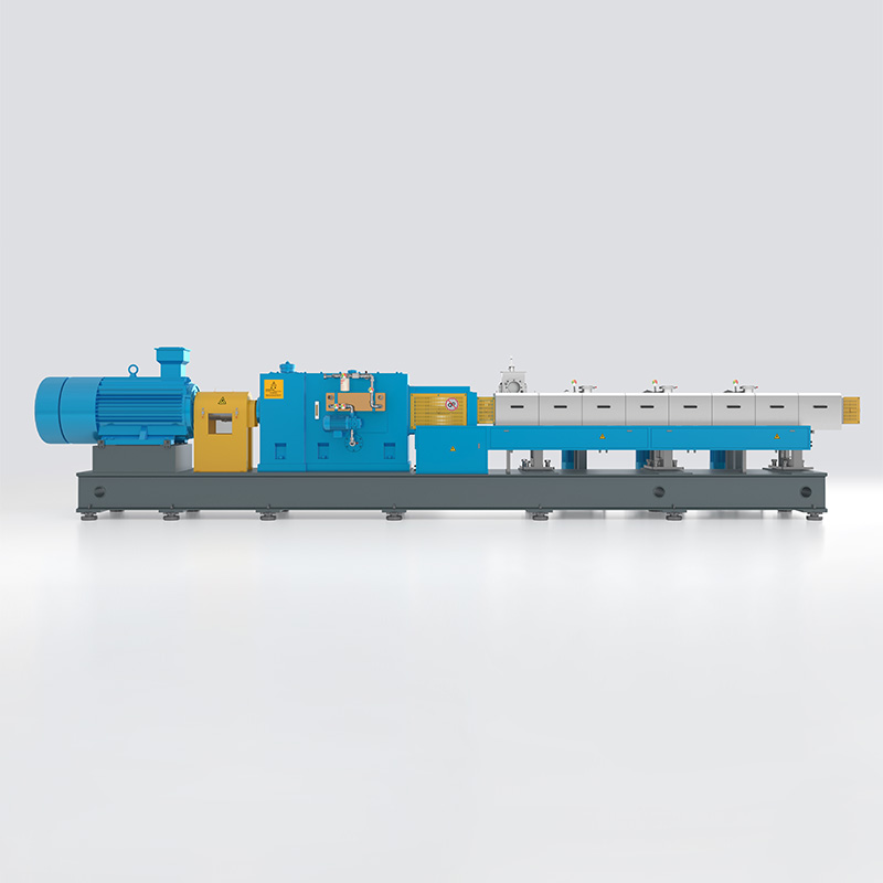 KTS High Performance Twin-Screw Extruder SeriesHigh-torque twin-screw extruder series for engineering plastics, with multiple model sizes and torque/speed options for compounding production lines.View Product →
Material flow stability starts at the feeder, not the barrel. Loss-in-weight dosing holds the active ingredient ratio within a fraction of a percent, while conical and side feeders handle powders that bridge or fluidise in a conventional hopper. Checking feeder range against the actual bulk density of your pigment is a five-minute exercise that prevents weeks of colour drift.
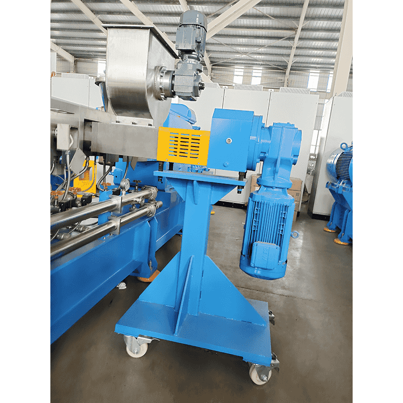 Side Feeder for Powder and Short-Fiber FeedingForced-feeding side extruder system for powder, short fiber, or premix, with negative-pressure barrel pumping to improve bulk density and feeding efficiency.View Product →
Pelletizing closes the loop. Strand pelletizing with a water bath stays the flexible choice for small lots and heat-sensitive colours; water ring hot-face cutting suits medium output and PVC-type compounds; underwater pelletizing handles high throughput and keeps dust emissions low. When an existing masterbatch twin-screw extrusion pelletising line is being re-rated, the pelletizer is frequently the bottleneck rather than the extruder.
 Underwater Pelletizing System for Dust-Reduced GranulationUnderwater die-face hot-cutting system that cools and shapes pellets in a closed water circuit, helping control dust and reuse cooling water.View Product →
Quality control and the defects that actually show up
Most complaints on a masterbatch line trace back to one of six causes. The table below is the short version of a fault-finding conversation worth having before installation.
| Symptom | Usual cause | Check or fix |
|---|---|---|
| Specks or gel particles in the final part | Insufficient dispersive work, cold feed, pigment agglomerates | Filter pressure value test, kneading block position, specific energy input |
| Batch-to-batch colour drift | Dosing inaccuracy, carrier mismatch | Verify gravimetric calibration, measure colour difference on a spectrophotometer |
| Bubbles or voids inside the pellet | Moisture in fillers, weak venting | Dry fillers before premix, check vacuum vent and melt temperature |
| Excess fines and dust | Wrong die hole diameter, poor strand cooling, worn blades | Water bath temperature, cutter speed, blade inspection |
| Die build-up and plate-out | Additive bloom, low-melting carrier | Reformulate carrier, polish die surfaces, review additive loading |
| Output drop with high filler | Feed zone flooding, torque limit reached | Move filler addition to a side feeder, review screw geometry |
Colour quality deserves a separate note. Precise dispersion in colour masterbatch work is closely tied to multi-stage feeding design: pigment added too early is over-sheared, added too late it never wets out. Where the screw cannot be changed, the feeding sequence usually can.


