


 ENG
ENG 中文简体
中文简体 русский
 عربى
عربىA compounder running a 40 mm twin-screw line rarely gets the same pellet twice after moving the same TPE formulation to a 75 mm machine. Shore A hardness drifts two or three points, oil migrates to the pellet surface, and the strand sticks to the conveyor. The screw diameter is seldom the real cause. What usually changed is torque density, liquid feeding capacity and the cooling path between die and pelletizer.
Here is the short answer: fix torque density first, then the feeding architecture, then the pelletizing route. In TPE compounding these three decisions interact far more strongly than they do in rigid PVC or unfilled polypropylene, because the melt is soft, the formulation often contains 30 to 50 percent oil by weight, and the polymer is either lightly crosslinked or not crosslinked at all.
The sections below work through each decision in order, with the tolerances, constraints and shop-floor trade-offs that actually decide whether a line holds rate.
Content
- 1 What Makes TPE Compounding Different from Rigid Plastic Compounding
- 2 Torque Density Is the First Specification to Fix
- 3 Feeding Architecture: Oil Injection, Filler and Side Feeders
- 4 Melt Temperature, Shear and Devolatilization
- 5 Pelletizing: Strand, Water Ring or Underwater
- 6 How a Complete TPE Compounding Line Fits Together
- 7 Frequently Asked Questions About TPE Compounding
What Makes TPE Compounding Different from Rigid Plastic Compounding
TPE is a family, not a single polymer. Styrenic block copolymer grades built on SEBS or SEPS, dynamically vulcanized TPV, thermoplastic olefin blends and TPU all pass through a compounding line, and each one asks something different of the barrel.
A SEBS-based grade commonly carries 100 to 200 phr of paraffinic process oil. That oil has to be pushed into the rubber mid-block without destroying the polystyrene end blocks that give the material its strength. A TPV contains a rubber phase that must be sheared hard enough to disperse evenly but not so hard that it degrades. A TPU is moisture sensitive, and residual water in the feed produces bubbles, surface defects and a measurable loss of mechanical properties.
| TPE family | Main compounding task | Feeding demand | Typical pelletizing route |
|---|---|---|---|
| SEBS / SEPS, oil extended | Distribute oil into the rubber phase without breaking the hard blocks | Downstream liquid injection plus gravimetric polymer feed | Water ring hot-face cutting or underwater cutting |
| TPV (PP / EPDM) | Dynamic vulcanization under controlled shear and residence time | Accurate curative and oil dosing | Underwater pelletizing |
| TPO blends | Disperse filler and pigment evenly | Side feeder for talc or calcium carbonate | Strand or water ring |
| TPU | Control moisture and limit thermal history | Dried feed, sealed conveying | Underwater pelletizing |
The common thread is that most TPE formulations carry at least two streams that rigid plastic compounding does not: a liquid and a low bulk density powder. Getting those two streams into the melt at a controlled rate is the single biggest determinant of whether the line runs steadily for a full shift. The same logic governs reaction extrusion processes, where the polymer is built in the barrel rather than merely melted, as described in the work on TPU reaction extrusion lines.
Torque Density Is the First Specification to Fix
Specific torque is the most useful single number for comparing co-rotating twin-screw machines. It is calculated as the torque on each shaft divided by the cube of the centre-line distance and expressed in Nm/cm³. A conventional compounding machine sits around 9 Nm/cm³. High-torque designs reach 11 to 13.5 Nm/cm³, and Kunwei states that its compounding-oriented machine reaches 14 Nm/cm³.
Figure 1: Widely used torque classes for co-rotating twin-screw compounding machines, with the 14 Nm/cm³ figure as stated by Kunwei for its compounding series.
Torque density converts directly into free volume and usable screw speed. Absorbing 150 phr of oil requires enough free volume for the liquid to be taken up without pooling at the die. Keeping a heat-sensitive elastomer intact requires reaching the necessary mixing work at low rpm. A higher-torque machine does both jobs at once, because the same output is delivered with fewer revolutions, so every kilogram of TPE sees less total shear history.
This is why high-torque twin-screw extruders have become the default choice for TPE and TPV compounding rather than an optional upgrade. The trade-off is mechanical: splined shafts, gearbox bearings and screw elements must all be rated for the load, so a 14 Nm/cm³ claim is only credible when the entire drive train is built to match it.
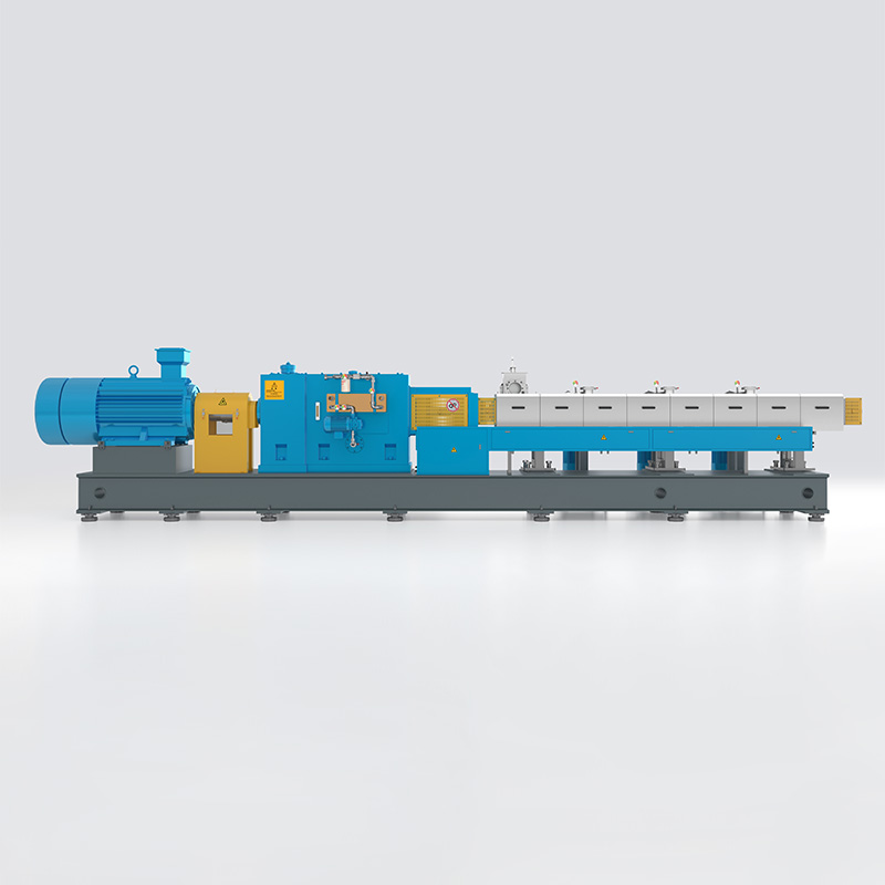 KTS High Performance SeriesTechnical ParametersView Product →
Feeding Architecture: Oil Injection, Filler and Side Feeders
Most TPE lines that fail to reach rated output are limited upstream, not at the screw. Three feeding decisions matter most.
Liquid injection point
Oil is injected into a barrel section downstream of a melt seal, never into the feed throat. The injection line should be heat traced, and flow should be controlled by a gear pump or a gravimetric dosing unit rather than by gravity. A typical SEBS formulation receives 100 to 200 phr of paraffinic oil, so a rate fluctuation of a few percent is visible immediately in Shore hardness.
Powder and filler addition
Talc, calcium carbonate, flame retardants and colour powders all have low bulk density and tend to fluidize in the feed throat, which starves the screw and causes surging. A side feeder that applies slight negative pressure at the entry point compacts the powder as it enters the barrel, raising the effective bulk density and stabilising the feed rate.
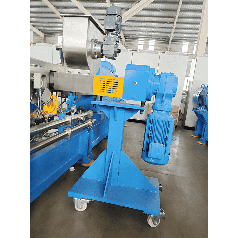 Side FeederThe side feeder is used for forced feeding of powder, short fiber or premix material, which can flexibly meet the process needs or increase the feeding amount. At the ...View Product →
Gravimetric control
Loss-in-weight feeders are standard on TPE lines because they correct automatically for density drift between batches of filler and for the gradual change in pellet bulk density as the oil content varies. Volumetric feeding is only adequate when the formulation is fixed and the raw materials come from a single qualified source.
Melt Temperature, Shear and Devolatilization
TPE melts are soft and heat sensitive, so the barrel profile usually rises to a mixing peak and then falls again before the die. A high die temperature makes the melt too fluid to cut cleanly, while an excessively cool die raises head pressure and can cause melt fracture.
Figure 2: Illustrative setpoints for an oil-extended SEBS compound, with a cool feed zone, a mixing peak near zone three and a falling profile toward the die.
Two vacuum ports are typical on a TPE line. The first sits immediately after the oil injection zone to strip light volatiles and any moisture carried in by the filler. The second sits close to the die to remove residual water. Running both ports at the same vacuum level is a common mistake; the downstream port normally needs the stronger vacuum because the melt is thinner and the free surface is smaller.
Pelletizing: Strand, Water Ring or Underwater
The pelletizing route decides dust level, pellet shape and how much operator attention the line demands.
| Route | How it works | Best fit | Watch out for |
|---|---|---|---|
| Strand with air-cooling conveyor | Melt exits the die, cools on a long conveyor, then is cut by a strand pelletizer | Low to medium output, easy visual inspection of melt quality | Oil-rich grades stick to the belt; higher dust level |
| Water ring hot-face cutting | Pellets are cut at the die face and thrown into a rotating water ring | Medium output, round pellets, moderate capex | Die-face temperature control must be tight |
| Underwater pelletizing | Cutting takes place in a water-filled chamber directly at the die plate | High output, closed system, low dust, good for soft melts | Higher capex; water treatment and screen changes needed |
For oil-rich SEBS grades, water ring and underwater cutting are usually preferred because the pellets are quenched the moment they are cut, which locks in shape before the oil can migrate. Strand pelletizing still has a place in trial work and in low-volume production, where the ability to see the strand is worth more than the extra output.
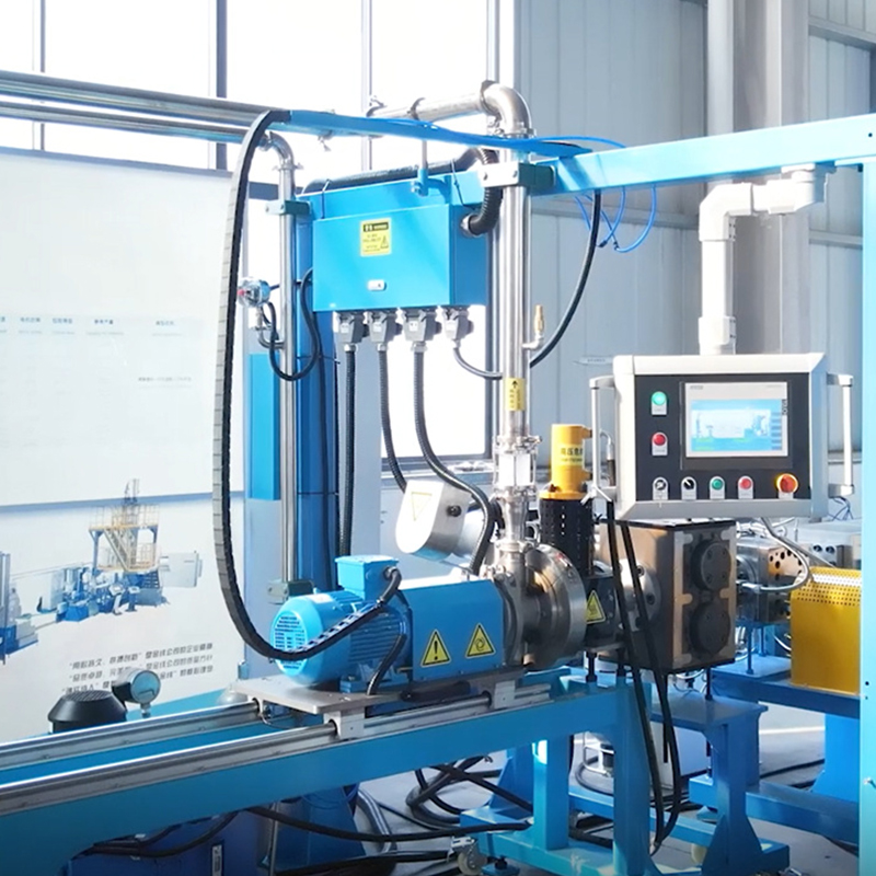 Underwater PelletizingUnderwater die surface hot cutting means that the material is cut into particles in water, and directly follows the water flow into the pipeline for cooling and shaping.View Product →
How a Complete TPE Compounding Line Fits Together
A TPE line runs in a fixed sequence, and each stage constrains the next. Feeders set the ratio, the side feeder sets the filler rate, the extruder sets the mixing work, and the pelletizer sets the final particle form.
Figure 3: Schematic arrangement of a TPE compounding train, from gravimetric feeding through the twin-screw extruder to the pelletizer.
Screw diameter selection follows the required output rather than the other way round. A machine range of roughly 8 mm to 177 mm covers everything from a laboratory trial of a few kilograms per hour to full industrial production, and trials on the small machine should be run at the same specific torque and the same residence time as the production unit, otherwise the scale-up will not hold.
Frequently Asked Questions About TPE Compounding
It is the melt blending of a thermoplastic elastomer base such as SEBS, SEPS, TPV or TPU with process oil, filler, antioxidant and colour, followed by pelletizing into free-flowing granules that can be injection moulded or extruded.
A high free-volume screw with kneading blocks for distributive mixing, a short dispersive section, and a melt seal placed before the oil injection port. Soft TPE melts usually lose quality with aggressive shear elements.
The oil was not fully absorbed before the die. Check that the injection point sits behind a proper melt seal, that the vacuum port downstream is working, and that die temperature lets the strand or die face skin over before cutting.
In TPE compounding the rubber phase stays uncrosslinked and is simply softened by oil. In TPV production the rubber phase is crosslinked inside the extruder while the plastic phase remains thermoplastic, which demands tighter curative dosing and residence time control.
Production lines commonly run 100 to 200 phr of paraffinic oil on SEBS grades, roughly half of the finished compound by weight. Beyond that, the limiting factor is usually melt cooling capacity rather than the injection system.
Often yes, but it needs review. The critical points are screw free volume, the availability of a downstream injection port and vacuum ports, the gearbox torque rating, and whether the pelletizer can handle a soft, slightly tacky melt.


